Working with Nodes
Master the building blocks of your workflows - learn how to add, configure, connect, and manage nodes
Nodes are the fundamental building blocks of FlowGenX workflows. Each node represents a specific operation, logic decision, or integration point in your automation. Understanding how to work with nodes effectively is key to building powerful, maintainable workflows.
Workflow Building Blocks
Comprehensive node system for building any automation workflow
Overview
Nodes are self-contained units of functionality that you connect together to create workflows. Each node has:
- Inputs: Where data flows into the node from previous steps
- Outputs: Where results flow to subsequent nodes
- Configuration: Settings that control the node's behavior
- Metadata: Properties like name, description, and error handling
Think of nodes like functions in programming - they take inputs, perform an operation, and produce outputs. By connecting nodes together, you build complex automation workflows that can handle everything from simple API calls to sophisticated multi-agent orchestrations.
Understanding Nodes
What is a Node?
A node is a visual representation of a single operation in your workflow. When you place a node on the canvas, you're adding a specific capability to your automation. Each node type is designed for a particular purpose, from triggering workflows to transforming data to making decisions.
Node Anatomy:
- Title Bar: Shows the node name (editable) and type icon
- Input Handles: Connection points where data enters (top or left side)
- Output Handles: Connection points where results exit (bottom or right side)
- Configuration Indicator: Visual feedback showing if the node is properly configured
- Action Menu: Appears on hover with options to clone, delete, preview, or detach
Node Categories
FlowGenX organizes nodes into six major categories, each serving different purposes in your workflow:
Trigger Nodes
Start workflow execution based on events
- • Webhook - HTTP endpoint triggers
- • Scheduler - Time-based execution
- • App Event - Application events
- • Manual - User-initiated runs
- • HTTP Listener - Listen for requests
Data Nodes
Manage data ingestion and storage
- • Ingest - Data ingestion
- • Knowledge Base - RAG operations
- • Sensor Watch - Monitor data
- • Transform - Reshape data
- • Filter - Conditional filtering
Integration Nodes
Connect to external systems and APIs
- • HTTP Request - REST API calls
- • SQL Execute - Database operations
- • Input/Output - I/O operations
- • Human-in-the-Loop - Approvals
- • Webhook Response - Send responses
Logic Nodes
Control workflow execution flow
- • If/Else - Conditional branching
- • Switch - Multi-path routing
- • ForEach - Iterate over collections
- • Split/Merge - Parallel execution
- • Loop - Repeat operations
Agent Nodes
AI-powered autonomous operations
- • ReAct Agent - Reasoning + Acting
- • Supervisor Agent - Multi-agent orchestration
- • Assistant Agent - Task assistance
- • Autonomous Agent - Self-directed
- • A2A Agent - Agent-to-agent protocol
Utility Nodes
Supporting workflow operations
- • Logger - Log information
- • Error Handler - Manage errors
- • Timer - Schedule delays
- • Sticky Note - Annotations
- • Group - Organize nodes
Execution Engine Compatibility
Each node supports specific execution engines: both (batch + LangGraph), batch (Airflow-style), or langgraph (AI agent workflows). Agent nodes typically require LangGraph, while traditional nodes work with both engines.
Adding Nodes to Canvas
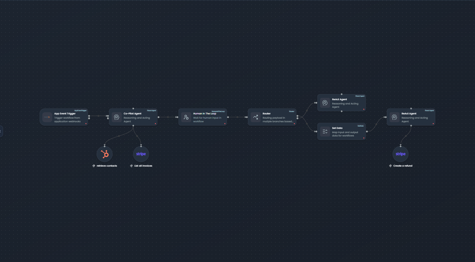
Workflow canvas with nodes, connections, and configuration options
There are two primary methods for adding nodes to your workflow canvas:
Method 1: Drag and Drop from Sidebar
The most common way to add nodes is by dragging them from the left sidebar onto the canvas.
Steps:
- Browse Categories: Click on a category in the left sidebar (Pipeline, Components, Agents, etc.) to expand it
- Find Your Node: Locate the node type you need - use the search bar if you know the node name
- Drag to Canvas: Click and hold on the node, then drag it onto the canvas
- Position: Release the mouse button to place the node at your desired location
- Auto-Save: The node is automatically added to your workflow
Sidebar Organization
Nodes are organized into logical categories: Pipeline (triggers, data, transformations), Components (integrations, utilities), Agents (AI agents, tools, memories), and specialized sections for specific use cases.
Method 2: Insert Between Existing Nodes
You can insert a node directly between two connected nodes without manually rewiring connections.
Steps:
- Click Edge: Click on the connection line (edge) between two existing nodes
- Select Node: A modal opens showing available node types organized by category
- Choose Node: Click on the node type you want to insert
- Auto-Connect: The new node is automatically inserted with connections established:
- Input connection from the source node
- Output connection to the target node
- Position Adjusted: The canvas may auto-adjust positions for optimal layout
Benefits:
- Saves time - no need to delete and recreate connections
- Maintains workflow logic flow
- Reduces errors from incorrect rewiring
Configuring Nodes
Every node needs to be configured before it can execute. Configuration determines how the node behaves and what data it processes.
Opening the Configuration Panel
There are multiple ways to open a node's configuration:
- Single Click: Click on a node to select it and open the right configuration panel
- Double Click: Double-click a node for quick access to configuration
- From Action Menu: Hover over a node and click the settings icon
The configuration panel slides in from the right side of the screen, displaying all configurable options for the selected node.
Inline Name Editing
You can quickly rename a node directly on the canvas without opening the full configuration panel:
- Double-Click Title: Double-click the node's title text
- Edit Mode: The title becomes editable with a text input field
- Type New Name: Enter a descriptive name for the node
- Save: Press Enter to save or Escape to cancel
- Auto-Update: The name updates immediately across the workflow
Best Practice: Use descriptive names like "Fetch User Profile" instead of generic names like "HTTP Request 1" to make your workflow self-documenting.
Configuration Form Structure
Node configuration is organized into three main tabs:
1. Detail Tab
Contains node-level properties that apply to all nodes:
| Field | Description | Default |
|---|---|---|
| Name | Display name shown on canvas | Node type name |
| Description | Optional description of what this node does | Empty |
| Retries | Number of retry attempts on failure | 0 |
| Retry Delay | Time to wait between retries (e.g., "5m", "30s") | 0s |
| Trigger Rule | Condition for when this node should execute | all_success |
2. Config Tab
Contains node-specific configuration fields. This is where you define the node's behavior:
- HTTP Request: API endpoint, method, headers, body
- SQL Execute: Connection, query, parameters
- If/Else: Condition expression
- ForEach: Collection to iterate over
- ReAct Agent: Model selection, tools, prompts
The fields in this tab vary significantly based on the node type and are dynamically generated from the node's configuration schema.
3. Schema Tab
Defines the data structure for inputs and outputs (available for LangGraph-compatible nodes):
- Input Schema: Expected data structure for incoming data
- Output Schema: Data structure this node will produce
- Type Information: Data types for each field (string, number, object, array)
- Required Fields: Which fields must be present
Common Configuration Patterns
Setting Static Values
The simplest configuration is providing static values directly:
{
  "api_url": "https://api.example.com/users",
  "timeout": 30,
  "enabled": true
}
Use static values when the data doesn't change between workflow runs.
Using Expressions
Expressions allow you to reference dynamic data from previous nodes:
{
  "user_id": "{{ upstream_node_name.output.user.id }}",
  "email": "{{ vars.customer_email }}",
  "timestamp": "{{ $.inputData[0].created_at }}"
}
Expressions are enclosed in double curly braces {{ }} and can reference:
- Upstream nodes:
{{ node_name.output.field }} - Global variables:
{{ vars.variable_name }} - Current node context:
{{ $.inputData }}
See the Working with Data guide for complete expression syntax.
Referencing Upstream Data
You can access data from any upstream node in your workflow:
{
  "customer_data": {
    "name": "{{ fetch_customer.output.name }}",
    "orders": "{{ get_orders.output.items }}",
    "total": "{{ calculate_total.output.sum }}"
  }
}
The configuration panel provides an Expression Context Explorer to browse available fields from upstream nodes.
Error Handling Setup
Configure how nodes handle failures:
{
  "retries": 3,              // Retry up to 3 times
  "retry_delay": "5m",       // Wait 5 minutes between retries
  "trigger_rule": "all_success"  // Only run if all upstream nodes succeed
}
Trigger Rules:
all_success: Run only if all upstream nodes succeeded (default)one_success: Run if at least one upstream node succeededall_failed: Run only if all upstream nodes failedone_failed: Run if at least one upstream node failedalways: Always run regardless of upstream status
Configuration Validation
FlowGenX provides real-time validation as you configure nodes:
Visual Indicators:
- Green Checkmark: Node is fully configured and valid
- Red Dot/Exclamation: Missing required fields or invalid configuration
- Yellow Warning: Optional issues or recommendations
Validation Checks:
- Required fields are filled
- Data types match expected types
- Expressions are syntactically correct
- Referenced nodes exist in the workflow
Complete Configuration Before Testing
Workflows cannot be executed until all nodes show valid configuration. The canvas displays a visual indicator for each node's configuration status, making it easy to identify nodes that need attention.
Connecting Nodes
Connections define the flow of data and execution order in your workflow. Understanding how to create and manage connections is crucial for building effective workflows.
Understanding Handles
Handles are the connection points on nodes:
-
Input Handles: Located at the top (horizontal layout) or left (vertical layout) of nodes
- Receive data from upstream nodes
- Labeled alphabetically: a, b, c, etc. for multiple inputs
- Target connection points
-
Output Handles: Located at the bottom (horizontal layout) or right (vertical layout) of nodes
- Send data to downstream nodes
- Labeled alphabetically: a, b, c, etc. for multiple outputs
- Source connection points
Creating Connections
To connect two nodes:
- Click Source Handle: Click on an output handle of the source node
- Drag: A connection line follows your cursor
- Drop on Target Handle: Release on an input handle of the target node
- Connection Created: The connection is established and data will flow when the workflow executes
Alternative Method:
- Click a source handle, then click a target handle (no dragging required)
Dynamic Handle System
FlowGenX uses an intelligent dynamic handle system that adapts to your connection needs:
Automatic Handle Creation:
- When you hover over a node, a special "new" handle appears
- Connecting to the "new" handle automatically creates an additional input/output
- Handle count increments automatically
- New handles are labeled with the next letter in sequence (a → b → c, etc.)
Example Flow:
- Node initially has 1 input and 1 output
- You connect a second node to the "new" output handle
- The output count increases to 2 (handles "a" and "b")
- A new "new" handle appears for potential third connection
This system allows you to create nodes with exactly the number of connections you need without pre-configuring handle counts.
Connection Validation
FlowGenX validates connections to prevent logical errors:
Valid Connections:
- ✅ Output to Input (correct direction)
- ✅ Compatible data types
- ✅ No circular dependencies
Invalid Connections:
- ❌ Input to Input or Output to Output
- ❌ Connecting a node to itself (direct loop)
- ❌ Creating circular dependencies that would cause infinite loops
The canvas prevents you from creating invalid connections and provides visual feedback when hovering over incompatible handles.
Special Connection Types
Different node types use specialized connection patterns:
Diamond Handles (Conditional Flow)
Nodes like Switch and Router use diamond-shaped handles to indicate conditional branches:
- Each output represents a different condition or route
- Only one path executes based on the evaluation
- Used for if/else logic and multi-path routing
Loop Connections
ForEach and Loop nodes create iterative execution:
- Special loop body subgraph
- Data flows through the loop multiple times
- Loop exit condition determines when to proceed
Parallel Branches
Split and Parallel nodes execute multiple branches simultaneously:
- Multiple output paths execute in parallel
- Use Merge node to synchronize results
- Improves workflow performance for independent operations
Connection Best Practices
Do
- • Connect nodes in logical execution order
- • Use descriptive node names before connecting
- • Test connections with preview/execute
- • Use parallel branches for independent operations
- • Keep workflows flowing top-to-bottom or left-to-right
Avoid
- • Creating circular dependencies
- • Crossing connection lines unnecessarily
- • Connecting nodes with incompatible data types
- • Building overly complex connection patterns
- • Forgetting to use Merge after Split operations
Node Actions
Each node provides a set of actions accessible via the hover menu. These actions help you manage, test, and organize nodes efficiently.
Action Menu Overview
When you hover over a node, an action menu appears with quick-access buttons:
Clone (Duplicate)
Icon: Copy icon
Creates an exact duplicate of the node including all configuration settings.
Use Cases:
- Building repetitive workflow patterns
- Creating templates for similar operations
- Testing variations of the same configuration
How it Works:
- Click the Clone icon on the node's hover menu
- A new node appears offset from the original
- All configuration is copied:
- Node name (with suffix to distinguish)
- All parameter values
- Schema definitions
- Error handling settings
- Connections are not copied - you'll need to reconnect the cloned node
Result:
- New node with unique ID and timestamp
- Same configuration as original
- Positioned near original for easy identification
Delete (Remove)
Icon: Trash icon
Removes the node and all its connections from the workflow.
Use Cases:
- Removing unnecessary nodes
- Simplifying workflow logic
- Cleaning up test or prototype nodes
How it Works:
- Click the Delete icon on the node's hover menu
- Confirmation modal appears (if enabled in settings)
- Confirm deletion
- Node and all connected edges are removed
Deletion is Immediate
Once confirmed, node deletion cannot be undone. All configuration and connections are permanently removed. Consider cloning important nodes before deletion for backup.
Detach (Remove from Group)
Icon: Unplug icon
Availability: Only visible for nodes that are children of a Group node
Removes the node from its parent group while keeping the node in the workflow.
Use Cases:
- Reorganizing grouped nodes
- Moving nodes between groups
- Breaking apart complex grouped structures
How it Works:
- Click the Detach icon (only appears on grouped nodes)
- Node is removed from the parent group
- Node position converts from relative (to group) to absolute (to canvas)
- Node remains in workflow at same visual position
- All connections are preserved
Result:
- Node is no longer part of the group
- Can be freely moved anywhere on canvas
- Group's visual boundary no longer includes this node
Preview/Execute (Test)
Icon: Play icon
Executes the node independently to test its configuration and see results.
Use Cases:
- Testing node configuration before running full workflow
- Debugging node behavior
- Validating API calls or database queries
- Previewing data transformations
How it Works:
- Click the Preview icon on the node's hover menu
- Node executes with current configuration
- Uses actual or sample input data:
- If upstream nodes exist, can use their outputs
- Can provide test input data manually
- Results appear in preview panel:
- Output data
- Execution logs
- Error messages (if any)
- Performance metrics
Benefits:
- ✅ Test without running entire workflow
- ✅ Validate configuration quickly
- ✅ Debug issues in isolation
- ✅ See actual API responses or query results
- ✅ Verify data transformations
Special Node Patterns
Some workflows require specialized node patterns to handle complex execution logic. FlowGenX provides several advanced patterns that work together to create sophisticated automation.
ForEach/Loop Pattern
Purpose: Iterate over collections of data, processing each item individually.
Use Cases:
- Process each order in a batch
- Send individual emails to a list of recipients
- Transform each record in a dataset
- Validate each item against business rules
How it Works:
The ForEach node splits a collection (array) into individual items:
- Configure the ForEach node with:
- Input collection (e.g.,
{{ upstream_node.output.items }}) - Optional batch size for grouping
- Input collection (e.g.,
- Create the loop body by connecting nodes after ForEach
- Each item flows through the loop body independently
- Use Loop (end) node to collect results and continue workflow
Configuration Example:
{
  "collection": "{{ fetch_orders.output.orders }}",
  "item_name": "current_order",
  "batch_size": 10  // Process 10 items at a time
}
Inside the Loop Body:
- Access current item with
{{ $.current_order }} - Each iteration runs independently
- Can use conditional logic (If/Else) within loop
- Results are collected automatically
Switch/Router Pattern
Purpose: Route execution to different paths based on conditions or values.
Use Cases:
- Route orders based on priority (high, medium, low)
- Handle different event types differently
- Apply different processing logic based on data characteristics
- Implement approval routing based on amount
How it Works:
The Switch or Router node evaluates an expression and directs flow to the matching branch:
- Configure condition expressions for each output path
- Data flows down the first matching path
- Each path can have completely different processing logic
- Optional default path for no matches
Configuration Example:
{
  "switch_on": "{{ order.priority }}",
  "cases": [
    {
      "condition": "high",
      "output": "a"  // First output handle
    },
    {
      "condition": "medium",
      "output": "b"  // Second output handle
    },
    {
      "condition": "low",
      "output": "c"  // Third output handle
    }
  ],
  "default_output": "d"  // If no match
}
Visual Pattern:
- Diamond-shaped handles indicate conditional outputs
- Each branch can have different downstream nodes
- Branches typically converge later (optional)
Split/Merge Pattern
Purpose: Execute multiple operations in parallel, then combine results.
Use Cases:
- Fetch data from multiple APIs simultaneously
- Process different aspects of data concurrently
- Perform independent validations in parallel
- Gather information from multiple sources
How it Works:
Split Node: Duplicates data to multiple output paths
- Takes single input
- Sends same data to multiple outputs
- All branches execute in parallel
Merge Node: Waits for all branches to complete and combines results
- Has multiple inputs (one from each branch)
- Waits for all upstream nodes to finish
- Combines data from all branches
- Single output continues workflow
Workflow Diagram:
              ┌──▶ API Call 1 ──┐
              │                  │
START ──▶ SPLIT ──▶ API Call 2 ──▶ MERGE ──▶ Process Results ──▶ END
              │                  │
              └──▶ API Call 3 ──┘
Benefits:
- ⚡ Faster execution (parallel vs sequential)
- 🔄 Independent failure handling per branch
- 📊 Gather data from multiple sources simultaneously
Group Pattern
Purpose: Organize related nodes visually and logically.
Use Cases:
- Group nodes by business function (e.g., "Customer Validation")
- Create reusable workflow segments
- Improve workflow readability
- Collapse complex sections for cleaner view
How it Works:
The Group node acts as a container:
- Place a Group node on canvas
- Drag nodes into the group boundary
- Grouped nodes show
parentIdrelationship - Group can be moved, and child nodes move with it
- Visual boundary shows group extent
Group Properties:
- Resizable: Adjust boundary to fit contents
- Collapsible: Hide/show grouped nodes (feature dependent)
- Movable: Move all child nodes together
- Stylable: Custom colors and labels
Best Practices:
- Group by logical function, not just visually
- Use descriptive group names
- Don't over-nest groups (keep it simple)
- Use groups for frequently reused patterns
Node Properties Reference
All nodes share a common set of properties, with additional type-specific properties for specialized nodes.
Common Node Properties
| Property | Type | Description |
|---|---|---|
| id | string | Unique identifier (UUID) for the node |
| type | string | Node type (e.g., HTTPRequest, ReactAgent, ForEach) |
| name | string | Display name shown on canvas (user-editable) |
| description | string | Optional description of node's purpose |
| input | number | Number of input handles (dynamic) |
| output | number | Number of output handles (dynamic) |
| retries | number | Number of automatic retry attempts on failure |
| retry_delay | string | Time to wait between retries (e.g., "5m", "30s") |
| component_params | object | Node-specific configuration parameters |
| upstream_tasks | array | IDs of nodes that feed into this node |
| downstream_tasks | array | IDs of nodes that receive data from this node |
| parentId | string? | ID of parent Group node (if grouped) |
Execution Modes
FlowGenX supports two execution engines, and nodes declare compatibility:
| Mode | Description | Best For |
|---|---|---|
| batch | Airflow-style batch processing with explicit task dependencies | ETL, scheduled jobs, data pipelines |
| langgraph | Event-driven execution for AI agents with dynamic routing | Agent workflows, conversational AI, dynamic logic |
| both | Compatible with both execution engines | General-purpose nodes (HTTP, database, logic) |
Node Property: supported_id
"both": Works in batch and LangGraph modes"batch": Only batch processing"langgraph": Only LangGraph (typically agent nodes)
Best Practices
Follow these guidelines to build maintainable, performant, and reliable workflows:
Naming Conventions
Good Names
- •
Fetch User Profile - •
Validate Order Total - •
Send Confirmation Email - •
Calculate Shipping Cost - •
Route by Priority
Action-oriented, specific, self-documenting
Poor Names
- •
HTTP Request 1 - •
Node - •
Temp - •
Test Node - •
asdfgh
Generic, non-descriptive, requires context to understand
Tips:
- Start with an action verb (Fetch, Calculate, Send, Validate, Process)
- Include the primary entity (User, Order, Email, Invoice)
- Keep names under 30 characters for readability
- Use consistent terminology across your workflow
When to Use Which Node Type
| Scenario | Recommended Node | Reason |
|---|---|---|
| Call external API | HTTP Request | Built-in testing, expression support, auth handling |
| Transform data structure | Transform / Data Transform | JSONPath, mapping, filtering capabilities |
| Process array items | ForEach + Loop | Iterate with full sub-workflow per item |
| Route based on conditions | Switch / Router | Multiple output paths with conditions |
| Parallel API calls | Split + HTTP Requests + Merge | Execute simultaneously, combine results |
| Human approval needed | Human-in-the-Loop | Pause workflow for manual review |
| AI reasoning required | ReAct Agent | LLM with tool use for complex decisions |
| Store workflow variables | SetData / Export Variable | Global variable access across nodes |
Configuration Organization
- Complete core configuration first before adding advanced features
- Test early and often using the preview/execute function
- Use expressions for dynamic data, static values for constants
- Document complex expressions in node descriptions
- Group related configuration logically (auth together, retry settings together)
Managing Complex Workflows
When workflows grow large:
- Use Groups to organize related nodes by function
- Leverage Auto-Layout to keep the canvas clean
- Break into sub-workflows if a workflow exceeds 20-30 nodes
- Add Sticky Notes to document complex logic sections
- Name nodes descriptively so new team members understand the flow
- Use consistent visual patterns (e.g., always use Split/Merge for parallel work)
Performance Considerations
Optimize For Speed
- ✓ Use parallel execution (Split/Merge) for independent operations
- ✓ Configure appropriate timeouts for external API calls
- ✓ Batch process items when possible instead of one-by-one loops
- ✓ Cache frequently accessed data in workflow variables
- ✓ Use filters early to reduce data volume through the workflow
Optimize For Reliability
- ✓ Configure retries for nodes that call external services
- ✓ Add error handling branches for critical operations
- ✓ Use trigger rules to control execution dependencies
- ✓ Log important state changes with Logger nodes
- ✓ Validate data early to fail fast on bad inputs
Troubleshooting
Common issues when working with nodes and their solutions:
| Issue | Possible Cause | Solution |
|---|---|---|
| Node won't connect | Wrong direction (output to output) | Connect from output handle to input handle |
| Configuration not saving | Validation errors in form fields | Check for red error messages, fix invalid fields |
| Preview/Execute fails | Missing required configuration or upstream data | Ensure all required fields filled, check upstream node outputs |
| Node shows red indicator | Required fields not configured | Open config panel, complete all required fields (marked with *) |
| Expression not working | Incorrect syntax or undefined reference | Use Expression Context Explorer to browse available fields, check syntax |
| Can't find node in sidebar | Wrong category or search term | Use sidebar search, check all categories, refer to node library docs |
| Circular dependency error | Node connections create a loop | Remove connection creating the cycle, redesign workflow flow |
| Node doesn't appear on canvas | Dropped outside visible area or zoom issue | Use "Fit View" button, check zoom level, search for node by name |
| Deleted node by accident | No built-in undo currently | Reload without saving (if unsaved), or recreate from node library |
| Handle labels overlap/unclear | Too many handles on small node | Zoom in, or redesign to use fewer direct connections |
Debug Workflow
When troubleshooting node issues:
- Use Preview/Execute to test nodes individually
- Check Execution Logs for error messages and data flow
- Verify Upstream Data - ensure previous nodes provide expected output
- Simplify - temporarily remove complex expressions to isolate issues
- Test with Static Data first before using dynamic expressions